Skip to ContentSkip to Footer
  • Reviews
  • News
  • Accessories & Tyres
  • Best Cars
  • Advice
  • Vans
  • Car Deals
  • Valuations
Subscribe

Find a car review

Make
  • Abarth
  • Alfa Romeo
  • Alpina
  • Alpine
  • Ascari
  • Aston Martin
  • Audi
  • Bentley
  • BMW
  • Bristol
  • Cadillac
  • Caterham
  • Chevrolet
  • Chrysler
  • Citroen
  • Corvette
  • Cupra
  • Dacia
  • Daihatsu
  • DFSK
  • Dodge
  • DS
  • Ferrari
  • Fiat
  • Ford
  • Great Wall
  • Honda
  • Hyundai
  • Ineos
  • Infiniti
  • Invicta
  • Isuzu
  • Iveco
  • Jaguar
  • Jeep
  • Kia
  • Koenigsegg
  • Lamborghini
  • Land Rover
  • LDV
  • LEVC
  • Lexus
  • Lotus
  • MAN
  • Marcos
  • Maserati
  • Maybach
  • Mazda
  • McLaren
  • Mercedes
  • MG
  • MINI
  • Mitsubishi
  • Morgan
  • Nissan
  • Noble
  • Perodua
  • Peugeot
  • Polestar
  • Porsche
  • Proton
  • Renault
  • Rolls-Royce
  • Saab
  • SEAT
  • Skoda
  • Smart
  • SsangYong
  • Subaru
  • Suzuki
  • Tesla
  • Toyota
  • Vauxhall
  • Volkswagen
  • Volvo
  • Westfield
Model
Features
  • Home
  • Land Rover

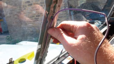
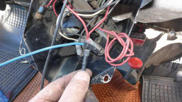
How to fit heated screens - pictures

by: Auto Express team
27 Sep 2017
Go to: How to fit heated screens
  • Step 1

    <span>Left and right-hand screens are available separately from heated&nbsp;</span><span class="skimlinks-unlinked">windscreens.com</span><span>. Relays, illuminated switch and fuse holder from Halfords.</span>

  • Fitting heated screens - 2
  • Fitting heated screens - 1
  • Step 2

    <span>The virtually invisible heated element wires run vertically with busbars top and bottom. Importantly, screens are road legal in most territories.</span>

  • Step 3

    <span>Disconnect the battery and remove the wiper arms. If fitted, remove the original air filter housing for access when routing the wires and siting the relays.</span>

  • Step 4

    <span>Remove the two rear view mirror screws and five large screws securing the fascia top rail. I used a screw bit and ratchet due to the limited access.</span>

  • Step 5

    <span>Remove both fascia end caps and undo the hidden set screws and bolts as shown here. Carefully place the heater controls out of the way.</span>

  • Step 6

    <span>Undo the fascia screws above the screen vents’ flap handles and remove the screws securing both demister vents on the top of the fascia.</span>

  • Step 7

    <span>Lift the fascia top rail inwards from the bulkhead and up, away from the dashboard. With any luck you won’t find any unexpected bulkhead corrosion.</span>

  • Step 8

    <span>With the fascia top rail removed, the bottom screw of the central screen finishing strip is accessed, using a magnetic screwdriver.</span>

  • step 9

    <span>If necessary, use a palette knife to slowly ease the finishing strip away from the old sealant. The sealant on mine had little adhesion and almost fell off.</span>

  • Step 10

    <span>Next, remove the screws holding the angled screen retainers. A magnetic screwdriver is best for the lower retainer where the screws inevitably fall out of reach otherwise.</span>

  • Step 11

    <span>I found it easiest to gently prise up the ends of the angle strips with a flat head screwdriver before using a palette knife for the rest.</span>

  • Step 12

    <span>Take note of the spacing between the frame and the old screens, typically 5mm all round. The glass should not be touching the frame.</span>

  • Step 13

    <span>Pressing on the outside of the glass close to the frame, work your way around the glass until it’s free. This is easy with old sealant.</span>

  • Step 14

    <span style="font-size: 0.8125em;">Remove all traces of the old sealant. Use thinners and a Scotch pad to thoroughly clean the frame surface of any residue without damage to the frame.</span>

  • Step 15

    <span>Some frames have more pronounced corner welds than this one. These must not be in contact with the glass when fitted, and should be ground down if necessary.</span>

  • Step 16

    <span>Partially lift the yellow film securing the connector strips away from the edge of each screen before fitting to avoid doing so when the sealant is used.</span>

  • Step 17

    <span>The sealing strip is applied by gently pressing it onto the frame. It’s important to keep its thickness consistent by not forcing or pulling it.</span>

  • Step 18

    <span>Apply the sealing strip to the angled finishers. I discovered that it’s better to trim any excess width before peeling off the backing. Use a sharp blade.</span>

  • Step 19

    <span>Rest the bottom of the screen on the aperture away from the sealant until you are happy with its position, approx 5 mm from the frame all round.</span>

  • Step 20

    <span>Once the sealing strip has grabbed the glass, it’s difficult to reposition the glass again, so take your time or you’ll have to start again.</span>

  • Step 21

    <span>I fitted the lower angle strip first to prevent the possibility of sealant sag. Align the screw holes before letting the sealing strip grab the glass.</span>

  • Step 22

    <span>Starting in the middle, fit all the screws but don’t tighten them fully. The sealant must cushion the glass so the angled sections don’t touch the screens.</span>

  • Step 23

    <span>Fit the other angle finishers, always tightening the screws outwards from the centre of each finisher. All three finishers should have a similar flush fit.</span>

  • Step 24

    <span>Apply sealing strip to both edges of the central ends of the screens. I used some trimmed excess from earlier. Alternatively, apply sealant to the finisher first.</span>

  • Step 25

    <span>If fitted, reroute the courtesy lamp wire using some sealing strip to hold it in position. Fit the finisher strip. Tighten the screws gradually.</span>

  • Step 26

    <span>Now trim any excess sealant from both sides of the frame using a very sharp blade. The sealant should come away cleanly, even in hot weather.</span>

  • Step 27

    <span>Next site your switch. I chose the lower dash because I prefer the illuminated switch clearly visible in use and because my lower dash isn’t perfect.</span>

  • Step 28

    <span>Wiring should following existing wires away from the bulkhead vents. This large hole was step drilled for the centrally routed positive main feeds.</span>

  • Step 29

    Always use grommets or rubber sleeving when routing wires through metal to prevent possibility of chafing of the 25 amp feeds.

  • Step 30

    <span>I fitted the relays inside the engine bay for easy access. Mark and drill their screw holes. LH relay for the LH screen, RH relay for the RH.</span>

  • Step 31

    <span>You’ll need two fuse holders, one for each screen feed. These fit between the battery main feed and the relays and must be rated for 25 amp capability.</span>

  • Step 32

    <span>You’ll need two fuse holders, I made a mini loom for the fuse holders to share a single terminal for connecting to the solenoid’s battery terminal, not the battery terminal direct.</span>

  • Step 33

    <span>Blue switch-to-relay feeds and red relay-to-screens feeds were fed through the bulkhead, then sleeved in the engine bay before fitting their terminals.</span>

  • Step 34

    <span>The screens’ negative feeds were run to each end of the dashboard beneath the parcel shelf liner tray having been heatshrink sealed first.</span>

  • Step 35

    <span>Black duct tape acts as barrier between the screen flat terminal feeds and bulkhead metal in the event of any chafing of wires.</span>

  • Step 36

    <span>The fully sealed connection, as done to all four screen feeds to minimise contact with metal or water in the depths of the dashboard.</span>

  • Step 3

    <span>By refitting the fascia top temporarily, I was able to determine how the feeds should be secured under the fascia without obstructions.</span>

  • Step 38

    <span>This piggyback terminal allowed the switch feeds to both relays to connect properly and securely to the single switch terminal.</span>

  • Step 39

    <span>The switch feed is taken from a fused 12 v feed that is not live when the ignition is off, such as a fog lamp or radio feed. This prevents battery drain</span>

  • Step 40

    <span>The switch feeds for an illuminated switch. If a separate warning lamp is used, your wiring will differ slightly.</span>

  • Step 41

    <span><span>The negative feeds from screens and relays all go to this earthing point on the steering column bracket. Note sleeving through bulkhead grommet</span></span> <span><span>&nbsp;</span></span>

  • Step 42

    <span>With 25 amp fuses in the inline fuse holders, the screens were warm to the touch 30 seconds after switching on. Heated screens at last!</span>

Recommended

Jaguar Land Rover confirms plans to cut 2,000 jobs
Jaguar
Jaguar

Jaguar Land Rover confirms plans to cut 2,000 jobs

JLR will trim its workforce over the next year – but company executives have confirmed that the changes won’t affect factory workers
18 Feb 2021
New Jaguar Land Rover electric car offensive: full details
Land Rover EVs
Jaguar

New Jaguar Land Rover electric car offensive: full details

New JLR boss announces that Land Rover is to launch six new pure electric models in the next five years, but the all-electric Jaguar XJ project has be…
15 Feb 2021
Jaguar Land Rover returns to profit in Q3 despite pandemic
JLR front end
Land Rover

Jaguar Land Rover returns to profit in Q3 despite pandemic

12 per cent of JLR sales plug-in hybrid or fully electric in third quarter of 20/21
29 Jan 2021
The future of Jaguar Land Rover: JLR design boss reveals all 
Land Rover

The future of Jaguar Land Rover: JLR design boss reveals all 

Gerry McGovern’s new role is helping to define JLR brands, not just the look, while encouraging designers to think big and dream...
26 Dec 2020

Most Popular

New 2021 Volvo C40 joins brand’s electric car line-up
Volvo C40 - front
Volvo C40

New 2021 Volvo C40 joins brand’s electric car line-up

The new Volvo C40 Recharge will take on electric car rivals such as the Tesla Model 3 and forthcoming Audi Q4 e-tron
2 Mar 2021
'Genesis’s aim is to lure Jaguar Land Rover customers'
Genesis
Opinion

'Genesis’s aim is to lure Jaguar Land Rover customers'

Mike Rutherford thinks luxury brand Genesis could take sales away from Jaguar Land Rover when it lands in the UK
1 Mar 2021
Nissan Re-Leaf: the electric car with an emergency power bank
Nissan Re-Leaf - header
Nissan Leaf

Nissan Re-Leaf: the electric car with an emergency power bank

The Nissan Re-Leaf concept shows how a family EV could power disaster-relief operations
1 Mar 2021
Skip to HeaderSkip to Content
Logo
  • Valuations
  • Contact Us
  • About Us
  • Evo
  • Carbuyer
  • Buyacar
  • Privacy Policy
  • Cookie Policy
  • Accessibility
  • Privacy Preferences

Subscribe to Auto Express magazine

Get the best of Auto Express
6 weeks for just £1 plus a free gift6 weeks for just £1 plus a free gift

Copyright © Dennis Publishing Limited 2021. All rights reserved.
Auto Express™ is a registered trade mark.

Follow us on FacebookFollow us on TwitterFollow us on YouTubeFollow us on Instagram