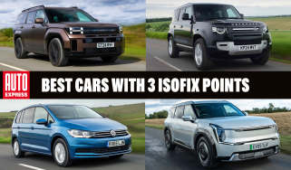
Land Rover Defender review
Land Rover’s reborn Defender has been a sales hit since it arrived, and subtle revisions haven’t done this 4x4 any harm at all

Our opinion on the Land Rover Defender
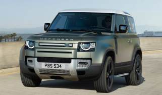
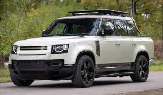
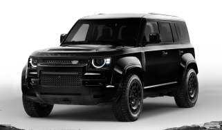
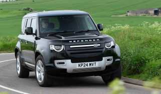
There’s nothing quite like the Land Rover Defender, and the most recent updates have done nothing to harm its desirability. It’s still a smart-looking large SUV that offers enough variety in the line-up to suit a wide range of buyers at the premium end of the market. It’s capable of delivering practical, multi-seat family transport, farm-friendly off-road ability, upmarket urban luxury or even supercar-baiting performance.
It’s not without its vices, with high purchase prices and running costs (even for the plug-in hybrid model), an almost bewildering array of body, trim and equipment options, plus its sheer size on the road counting against it. But the smart looks, spacious cabin and rugged design mean it continues to be a desirable and upmarket 4x4.
About the Land Rover Defender
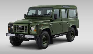
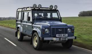
When the reinvented Land Rover Defender arrived in 2020, it certainly divided opinion between those that wanted a modern inte pretation of the company’s classic 4x4 and others who wanted a simple update of what had come before.
Looking at the sales figures, it’s obvious that Land Rover went in the right direction with the car, known internally as the L663, because there’s been little evidence of waning demand even after six years. But that hasn’t stopped the firm giving the Defender a few tweaks, with the 2026 model year benefiting from updates to its design and user-friendliness.
Used - available now

2024 Land Rover
Defender
36,484 milesAutomaticDiesel3.0L
Cash £59,890
2025 Land Rover
Defender
21,384 milesAutomaticDiesel3.0L
Cash £62,990
2022 Land Rover
Defender
29,945 milesAutomaticDiesel3.0L
Cash £44,950
2024 Land Rover
Defender
32,220 milesAutomaticPetrol3.0L
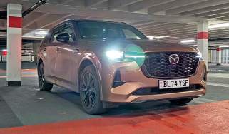
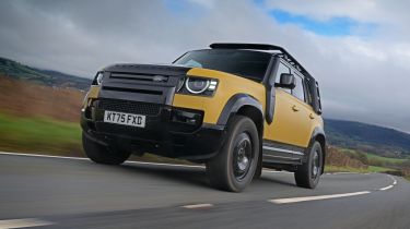
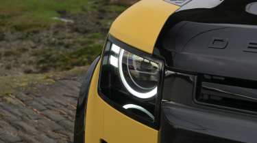
Cash £60,349The changes are subtle on the outside, with a new headlight signature and flush-fitting tail-lights with smoked lenses at the rear, while new paint and wheel options have been added. Inside, there’s a larger 13.1-inch touchscreen, and adaptive off-road cruise control has been added to the suite of terrain-tackling software. A new driver-attention sensor has also been introduced, while fresh accessory packs offer more personalisation.
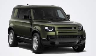
The Defender continues to be offered in three-door 90, five-door 110 and long-body 130 guises, with the latter two fitted with air suspension as standard.
Land Rover prices and latest deals
Prices start from a touch over £57,000, with the 110 costing from £63,000 and the 130 starting at £84,000. The commercial versions, called the 90 Hard Top and 110 Hard Top, start from just under £59,000, while the flagship Defender Octa is the V8 performance model with 626bhp and a £150,000 price tag.
Don’t forget, you can save when you configure your perfect Land Rover Defender through the Auto Express Buy a Car service. We also have a range of Defender leasing deals and used Defender models to choose from.
Performance & driving experience
Pros |
|
Cons |
|
One big upgrade that the Defender had over the classic model was a switch to unibody construction, with a platform that was shared with the previous-generation Range Rover.
All models are four-wheel drive, featuring an eight-speed automatic gearbox with low-range, plus a centre diff lock. Air suspension is standard on the Defender 110 and 130, while it’s an option on the Defender 90.
| Model | Power | 0-62mph | Top speed |
| Defender 110 D250 | 246bhp | 8.3 seconds | 117mph |
| Defender 110 P300e | 296bhp | 7.6 seconds | 119mph |
| Defender 110 Octa | 626bhp | 4.0 seconds | 155mph |
Performance, 0-60mph acceleration and top speed
There is a selection of engines available in the Defender, and they vary according to bodystyle and trim. The short-wheelbase Defender 90 comes with a choice of D250 or D350 diesel mild-hybrids in S, X-Dynamic SE and X-Dynamic HSE specs, or there’s a P425 petrol V8 offered in the higher-spec Defender X and V8 versions.
Even the base cars are reasonably quick with punchy performance, and no model is slower than eight seconds from 0-62mph.
The five-door 110 is the backbone of the Defender line-up and is offered with the widest range of engines. The 90’s options are carried over, but they are also joined by a plug-in hybrid powertrain based on a 2.0-litre four-cylinder petrol unit. This set-up is tuned to make 296bhp and comes with a 15.4kWh battery and an electric motor for zero-emissions driving.
The Defender 130 only comes with the D350 diesel or P425 and P500 versions of the 5.0-litre supercharged V8. Finally, the Defender Octa features a BMW-sourced 4.4-litre twin-turbo V8 that makes 626bhp, giving it the fastest acceleration of the lot, managing 0-62mph in exactly four seconds.
Town driving, visibility and parking
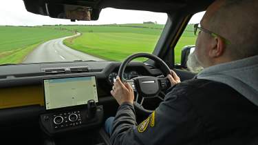
At more than two metres wide, the Defender isn’t really set up for urban roads. Light steering helps at low speeds, but it feels a little slow to get from lock to lock. Rear visibility isn’t great, courtesy of the spare wheel on the back door, but standard-fit parking sensors and a 360-degree camera system help with positioning, with a high-resolution and adjustable feed on the central touchscreen.
Travelling at lower speeds in the Defender 110 is comfortable thanks to the model’s air suspension, while the engines are responsive, so you can easily keep pace with urban traffic.
Country road driving and handling
That fulsome width (and 5.4 metres length in 130 guise) mean the Defender weighs anything from 2.2 to 2.7 tonnes, so it’s not a natural on twisting roads. With this in mind, the Defender performs surprisingly well, though. Air suspension copes admirably with the car’s weight, and while there is significant body roll, the Land Rover maintains its composure over mid-corner bumps.
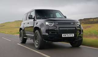
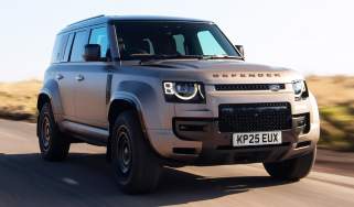
The diesel engines deliver good responses, but if you’re looking for a performance machine, then the Octa ticks that box. It uses the same advanced air-suspension system as the Range Rover Sport SV, so it delivers flat cornering and cross-country driving that can match plenty of sports cars and hot hatchbacks, which is pretty astounding for a 2.6-tonne SUV.
Motorway driving and long-distance comfort
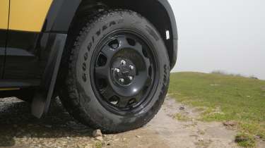
Boxy proportions don’t spoil the Defender’s ability at the national limit, and the car is nearly as refined as a Range Rover at higher speeds. Add the Explorer Pack and you get a steel roof rack, but while it has aerodynamically sculpted bars, it still generates additional noise at 70mph. The same goes for all-terrain tyres: add these and there’s a constant hum from below.
Air suspension helps the Defender soak up bumps well, and there’s just a bit of bounce over larger expansion joints, while the engines all deliver strong responses.
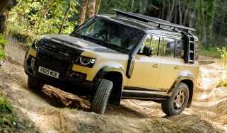
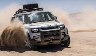
Off road
Although the Defender is great on the road, it also delivers more off-road ability than any owner is ever likely to need. The air suspension can be raised for extra ground clearance, while activating the locking diffs and low-range gears at the push of a button really takes the strain out of driving off the beaten track. As ever, Land Rover’s Terrain Response software means you can tailor the car’s systems to any surface, while options such as off-road adaptive cruise control (new for 2026) and the ClearSight forward visibility system only help to boost its ability.
"While there are plenty of performance SUVs that are rapid in a straight line, not many have the kind of all-round ability that the Defender OCTA can deliver. It comes with the same ‘6D Dynamics’ adaptive air-suspension system that’s fitted to the Range Rover Sport SV, and this gives the car a broad spread of ability." - Dean Gibson, senior test editor.
MPG & running costs
Pros |
|
Cons |
|
The first obstacle to Defender ownership is the car’s list price. With the line-up starting from around £57,000 and more than doubling at the top of the range, the car is priced to match rival premium SUVs, but high demand shows that many are happy to stump up.
Land Rover’s online configurator proudly boasts of mild-hybrid technology on the petrol and diesel Defenders, but the SUV’s economy isn’t anything to write home about. The diesels use a 3.0-litre in-line six, so they are more focused on pulling power than fuel efficiency, and official economy of 33.8mpg for the D250 in the lightest Defender 90 body is as good as it gets. However, it’s worth noting that the more powerful D350 is only 0.1mpg poorer, so there isn’t a big penalty to pay when choosing the meatier motor.
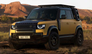
In our test of the 110 Trophy Edition, we saw a return of 29.1mpg on a round trip from London to Wales that involved plenty of motorway driving, which wasn’t far off the car’s official figure of 31.2mpg. Combine our test figure with the Defender’s vast 89-litre fuel tank, and there’s a potential range of 570 miles on offer.
You’re unlikely to be buying a V8 petrol if fuel economy is important to you. Official figures are in the 20mpg range for the supercharged V8 Defender 90 and 110, and poorer still for the multi-seat Defender 130. The high-performance Octa has the best claimed efficiency, with its BMW-sourced twin-turbo V8 offering a claimed 21.4mpg. When we tested the Octa, we saw a consistent 19mpg, even when using it as intended.
The P300e plug-in hybrid has claimed fuel economy of 110.5mpg, but we covered nearly 13,000 miles when living with an older-specification P400e and averaged only 30mpg. This is close to what you’d expect from a diesel Defender – a car that will be cheaper to buy in the first place.
| Model | MPG | CO2 | Insurance group |
| Defender 110 D250 | 33.1mpg | 223g/km | 40 |
| Defender 110 P300e | 110.5mpg | 58g/km | 42 |
| Defender 110 Octa | 21.4mpg | 298g/km | 50 |
Electric range, battery life and charge time
Land Rover only fits the P300e powertrain to the Defender 110, and the 15.4kWh drive battery is located under the boot floor. This offers a claimed range of 31 miles in all-electric mode.
A maximum charging speed of 40kW can get the battery from 0-80 per cent capacity in half an hour, while a full charge from a 7kW home wallbox takes two and a half hours.
| Model | Battery size | Range | Insurance group |
| Defender 110 P300e | 15.4kWh | 31 | 40 |
Insurance groups
Even the most basic Defender 90 with the D250 diesel sits in insurance group 41 out of 50, while the range-topping V8 Octa is in the highest band.
There have been historic issues of owners not being able to get insurance quotes for their cars, but Land Rover has taken measures to help reduce the risk of vehicle theft, which should help when it comes to premiums.
Tax
The increase in the luxury car tax threshold from £40,000 to £50,000 doesn't do any favours for the Defender, because it only applies to electric vehicles, so it’s £620 for road tax in years two to six.
Company car drivers may be drawn to the P300e’s emissions of 61g/km, but many plug-in hybrid alternatives, such as the BMW X5 xDrive50e, are in a much lower Benefit-in-Kind band and will be cheaper business cars. Then there are all-electric alternatives such as the seven-seat Kia EV9. These offer much more space inside than a Defender, and their monthly BiK costs are far lower, too.
Depreciation
Defender owners will benefit from good residual values when the time comes to sell. Our market data suggests that the Defender 90 retains between 53 and 67 per cent of its original value after three years and 36,000 miles of ownership, while the 110 is even better, ranging from 57-68 per cent.
The Defender 130 is a bit more of a niche model and will be worth between 47 to 55 per cent of its list price after the same period. That’s still much better than a BMW X5, for example, which will only retain between 40 and 53 per cent of its value when new.
Interior, design & technology
Pros |
|
Cons |
|
Land Rover did a great job of bringing the Defender into the 21st century, and the latest updates have only introduced subtle tweaks to the lights. There’s a nod to the previous model regarding the car’s overall look, but this 4x4 is definitely at the cutting edge in terms of off-road ability and on-board technology.
Interior and dashboard design
While the Defender sits at the premium end of the market in terms of price, Land Rover had to ensure it didn’t steal sales from its Range Rover models, so it has been given a more rugged appearance than those cars.
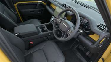
One distinctive feature on the dashboard is what Land Rover calls the cross-car beam, which can be specced to match the car’s exterior colour. On the Trophy Edition, this adds some brightness to the dash, and it’s not overbearing because the touchscreen breaks up the dashboard layout.
There’s a straight-edged theme to the rest of the interior, while elements such as the exposed screw heads and rough powder-coated metal steering wheel spokes tap into the rugged side of the Defender’s character.
Materials and build quality
The quality of the materials in the Defender is excellent, and it feels as if it will withstand tough knocks. Land Rover offers Resist synthetic leather and Resolve textile seat upholstery that gives an upmarket feel, yet should be easy to keep clean. The cabin trim feels up to taking some serious abuse before working loose, although how much you’d want to test that in a car that can cost well in excess of £60,000 is open to debate.
Infotainment, sat-nav and stereo
Following the latest updates, all Defenders feature a 13.1-inch touchscreen system. This offers more real estate for the car’s many functions, although it still nominally splits the display into three columns across the screen.
There are shortcuts on either side for quick access to various settings, while the screen response is quick and the graphics are sharp.
Updates to the Range Rover line-up have stripped that car’s dash of most of its buttons, but the Defender still has a bank of physical climate controls on a panel below the main screen. Two rotary dials adjust the temperature, but press them and the seat heating function appears, while controls between them switch their purpose to adjust fan speed or some Terrain Response settings.
The digital driver’s display has clear graphics and plenty of information, all controlled via the touch pads on the steering wheel. These are unlabelled, so it might take a little time to get familiar with how the system works.
“You don’t get the same squashy dashboard finishes you’ll find on a Bentley Bentayga or even a Mercedes G-Class, but the Land Rover’s Suedecloth steering wheel is lovely to hold, and we found the seats comfortable yet supportive, even after a long day of driving.” - Richard Ingram, deputy editor.
Boot space & practicality
Pros |
|
Cons |
|
Considering how large the Defender is, interior space is fine rather than outstanding, but there are a number of seating options on offer. Of course, the three bodystyles offer varying degrees of practicality, with the 90 model better suited to those who only need occasional rear seats or boot space, not both at the same time.
The 110 is a good size for a five-seat family car, but can be upgraded to a seven-seater if needed, while the 130 has up to eight seats available in its extended body.
Dimensions and size
At just over two metres wide, the Defender will be tricky to position between width restrictions or in parking spaces, but 360-degree cameras and parking sensors will at least help with this.
Air suspension is standard on all bar the base Defender 90s, and this comes with an Access Height setting that lowers the car to help most passengers climb aboard. Grab handles are set low at the ends of the dashboard to aid access, but they aren’t that useful to help pull yourself in.
| Dimensions comparison | |||
| Model | Land Rover Defender 110 | Ineos Grenadier | Toyota Land Cruiser |
| Length | 4,758mm | 4,896mm | 4,925mm |
| Width | 2,008mm | 1,930mm | 1,980mm |
| Height | 1,927mm | 2,036mm | 1,935mm |
| Wheelbase | 3,022mm | 2,920mm | 2,850mm |
| Boot space | 786 litres | 1,255 litres | 742 litres |
Seats & passenger space
Land Rover specialises in a range of seating options for its cars, but even the standard chairs in the Defender are comfortable and supportive.
Space is good, with the wide cabin providing enough room up front that you can replace the centre console with an optional jump seat. Stick with the standard layout, and cabin storage is generous. The console has space for a lower tray with sliding storage above it, two deep cup-holders and a wide armrest bin that can be upgraded to a coolbox at extra cost.
In the back, the three seats offer good support and there’s a flat floor for every passenger. Separate climate controls feature on higher-spec models, while there are two USB sockets for connecting devices.
Land Rover offers the option of a third row in the Defender 110, but if you really need more space, then the eight-seat Defender 130 is a better option. This can also be had with the firm’s ‘Super 7’ layout, which swaps the middle row for two plush captain’s chairs.
Boot space
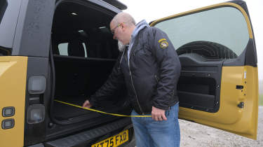
All Defenders come with a side-hinged tailgate with a spare wheel attached. While the door is large and heavy, it’s easy enough to open and close, but you do need to ensure you have enough space behind the car for it to swing open unobstructed.
In practical terms, the Defender 90 is hampered by its short wheelbase and three-door layout, and the boot offers a measly 297 litres of space in five-seat mode – that’s less than a lot of superminis. Fold the seats flat and there’s 1,263 litres of space on offer.
The Defender 110’s extra length boosts its cargo volume to 786 litres in five-seat mode, or 1,875 litres with the rear bench folded. The P300e plug-in model is a bit smaller, at 696 litres, or 1,759 litres with the seats flat. The Defender 130 is truly vast, with 1,094 litres to play with as standard, or a van-like 2,078 litres with all seats folded.
The cargo area has a flat, square floor, but it’s quite high off the ground for lifting heavier items in and out. Uniform sides mean it’s easy to load, while the Defender features a canvas load cover with elasticated straps that stretches across the load bay. Folding the seats is straightforward, with the seat bases flipping forward and the headrests folding down to tuck in behind them to leave a flat floor.
Towing
Most versions of the Defender have a maximum towing limit of 3,500kg, although the plug-in hybrids and heavy Defender 130 have a reduced braked trailer towing rating of 3,000kg. In either case, that’s a lot more than the 2,700kg capacity of the best-performing plug-in hybrid BMW X5 xDrive50e.
The Towing Pack includes an electrically deployable tow bar, and the 13-pin electric point is located within easy reach. You can also add an Advanced Tow Assist function where you can use the rotary dial from the Terrain Response system to steer the vehicle in reverse. Pull the dial up while reversing, and you can steer the car and caravan/trailer using the moving directional arrows on the screen, which show where the car will go. We think that’ll be helpful for those who struggle with this task.
“That side-hinged tailgate means you have to plan where you’re going to park so that you can open it easily, and it needs more space than the Ineos Grenadier’s back doors to open.” - Dean Gibson, senior test editor.
Reliability & safety
Pros |
|
Cons |
|
There have been issues in the past with the electrical systems on Land Rovers proving temperamental, but the Defender features over-the-air updates that should help keep cars working correctly.
The model earned a five-star safety score at launch in 2020, but Euro NCAP’s six-year statute means it will need to be retested to retain that. One highlight of the safety systems is the ease with which you can set them up to your liking. Spend a bit of time configuring the warnings, and then your presets can be activated with two presses of a button on the steering wheel.
| Euro NCAP safety ratings | |
| Euro NCAP safety rating | Five stars (2020) |
| Adult occupant protection | 85% |
| Child occupant protection | 85% |
| Vulnerable road user protection | 71% |
| Safety assist | 79% |
Buying and owning
- Best buy: Land Rover Defender 110 X-Dynamic SE D350
There are so many options within the Defender line-up that you can basically spec a car up to your heart’s desire. Ignoring the need for more than five seats, we’d definitely be looking at a Defender 110 body as a starting point, because it’s more versatile than the 90 and better proportioned than the 130.
The diesels offer a good mix of performance and efficiency, and the more potent D350 doesn’t suffer much of a penalty when compared with the D250.
In terms of trim, no car is poorly equipped, but the X-Dynamic SE offers a bit more kit when compared with the entry-level S version. There are 20-inch wheels, heated full synthetic leather memory seats, surround cameras and parking sensors, as well as air suspension and the Terrain Response system.
In terms of options, the choice is as wide as your budget will allow. We’d recommend adding air suspension to models that don’t have it, while different wheels are down to personal taste. We like the 20-inch alloys of the Trophy Edition, but in white, while there are different exterior graphics and extras such as side steps, a roof rack and panniers mounted on the outside of the windows. The Towing Pack, meanwhile, adds a retractable towbar to take advantage of the D350’s 3.5-tonne hauling capacity.
Land Rover Defender alternatives
Positioned as a premium SUV, although not quite at the same level as a Range Rover, the Defender has a whole bunch of tough competitors – but it’s also a focused off-roader, so it has to fight on two fronts. The likes of the Audi Q7, BMW X5, and Mercedes GLE are alternatives when considering the quality on offer.
If you want something with similar off-road prowess, the Toyota Land Cruiser is a close rival, while top-spec V8 versions of the Defender aren’t too far away price-wise from a Mercedes G-Class.
Land Rover Defender P400e long-term test
Back in 2023, our then editor-in-chief, Steve Fowler, ran a plug-in hybrid Land Rover Defender 110 P400e for a long-term test. He loved a number of thoughtful interior design touches that just made life that little bit easier, including the ability to have updates carried out over the air, meaning he didn’t have to endure time-consuming trips to the Land Rover dealer.
He even lent the Defender to his friend Adrian Chiles, who took it on an extended European holiday. However, such a trip with no charging, plus Steve’s regular trips to Liverpool and back to watch the football, meant fuel consumption overall was around 30mpg, so he reckoned he’d have been better off choosing the cheaper to buy diesel instead.
Frequently Asked Questions
Setting fuel economy aside, there are few other cars that are as easy to get on with, as capable, and as versatile as the current Land Rover Defender. If you can afford one, you won’t be disappointed
Deals on the Defender and alternatives